


软件

产品


🍺相关文章汇总如下🍺:
在后处理中读取结果的步骤一般是:
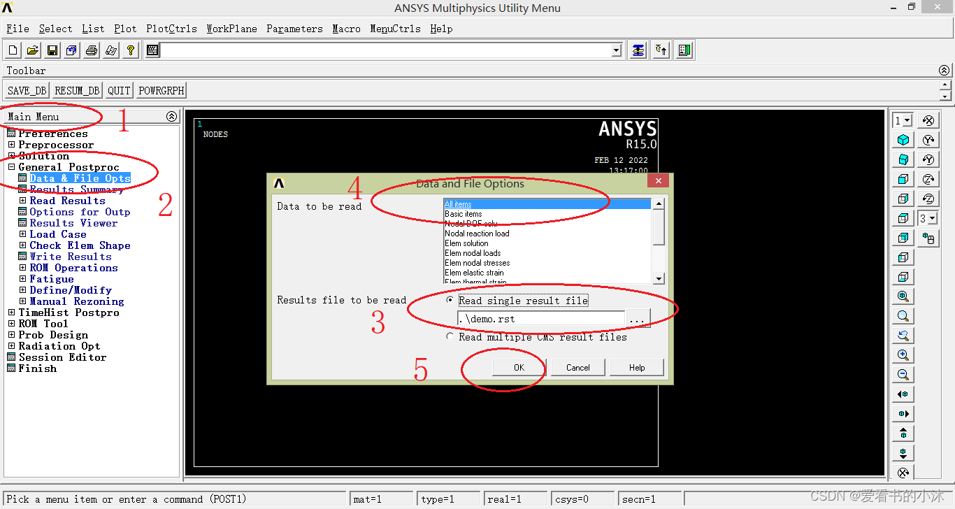
finish
/post1
/cwd, d:/test
file, demo.rst
set, first
allsel
nsel, stat
eplot ! 或 gplot、nplot、 kplot
/view, 1, 1,1,1
/replot
(1) 弹出窗口 ,并列出基本信息,同时列出每个载荷步的标题。
set, list
(2)读取某个载荷步或某个子步的求解结果
set,list,0 或者 set,list,1 读取结果文件,并列出每个载荷步的基本信息
set,list,2                      读取结果文件,并列出基本信息,同时列出每个载荷步的标题
set,first 从结果文件中读取第一个载荷步
set,last 从结果文件中读取最后一个载荷步
set, next 从结果文件中读取下一个载荷步
set, previous 从结果文件中读取前一个载荷步
set,near,,,time 从结果文件中读取最接近该时间的载荷步
set, next, 3 从结果文件中读取下一个载荷步的第三个子步`
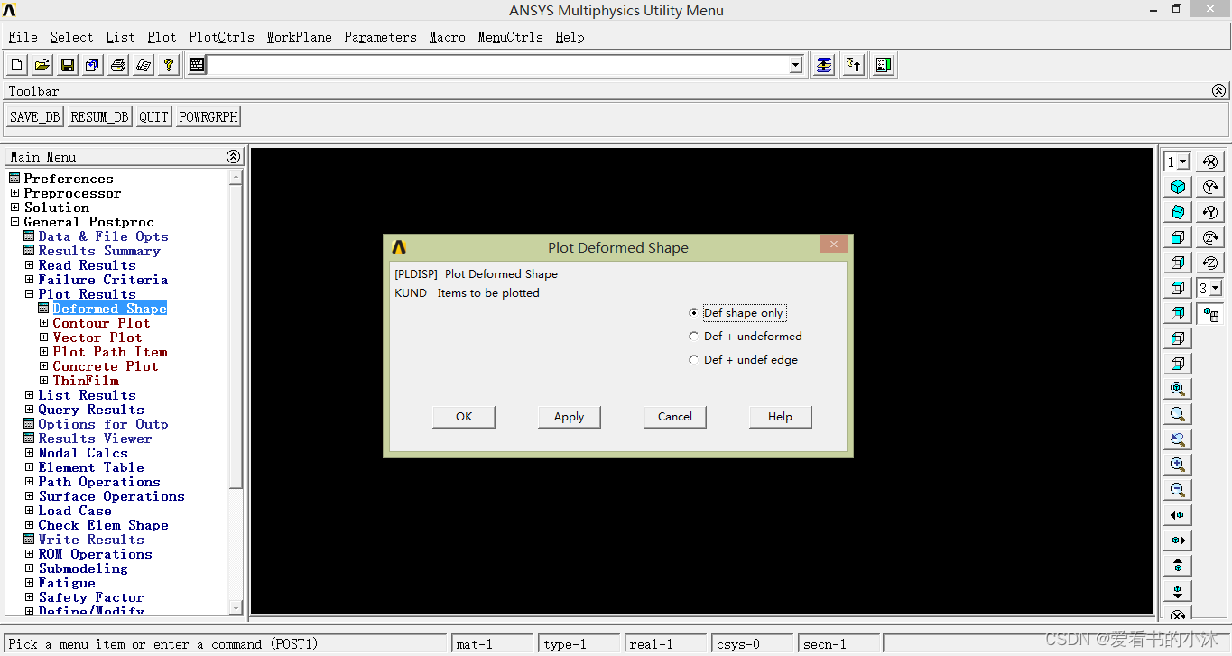
PLDISP, 0
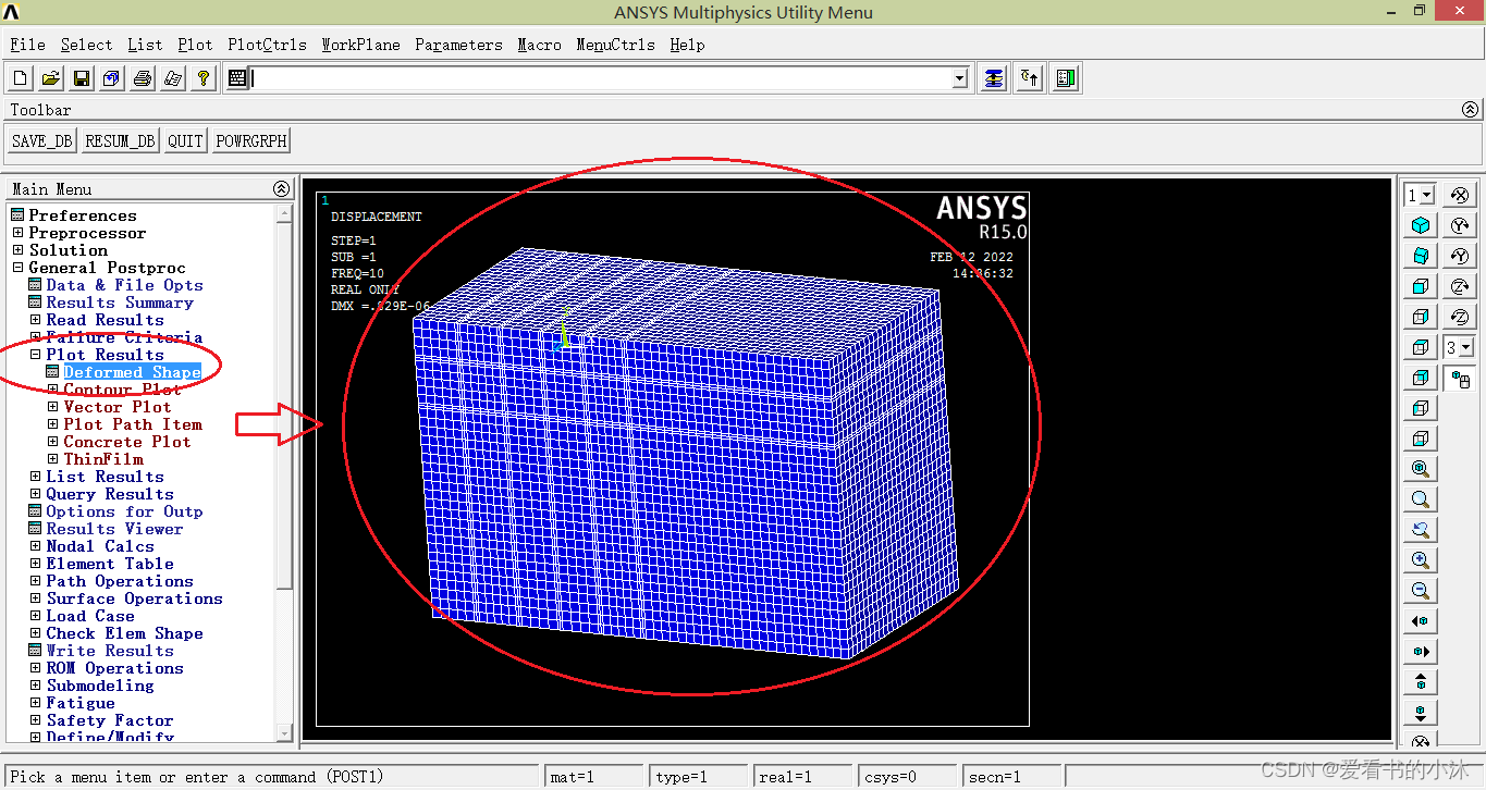
绘制节点的位移等值线图: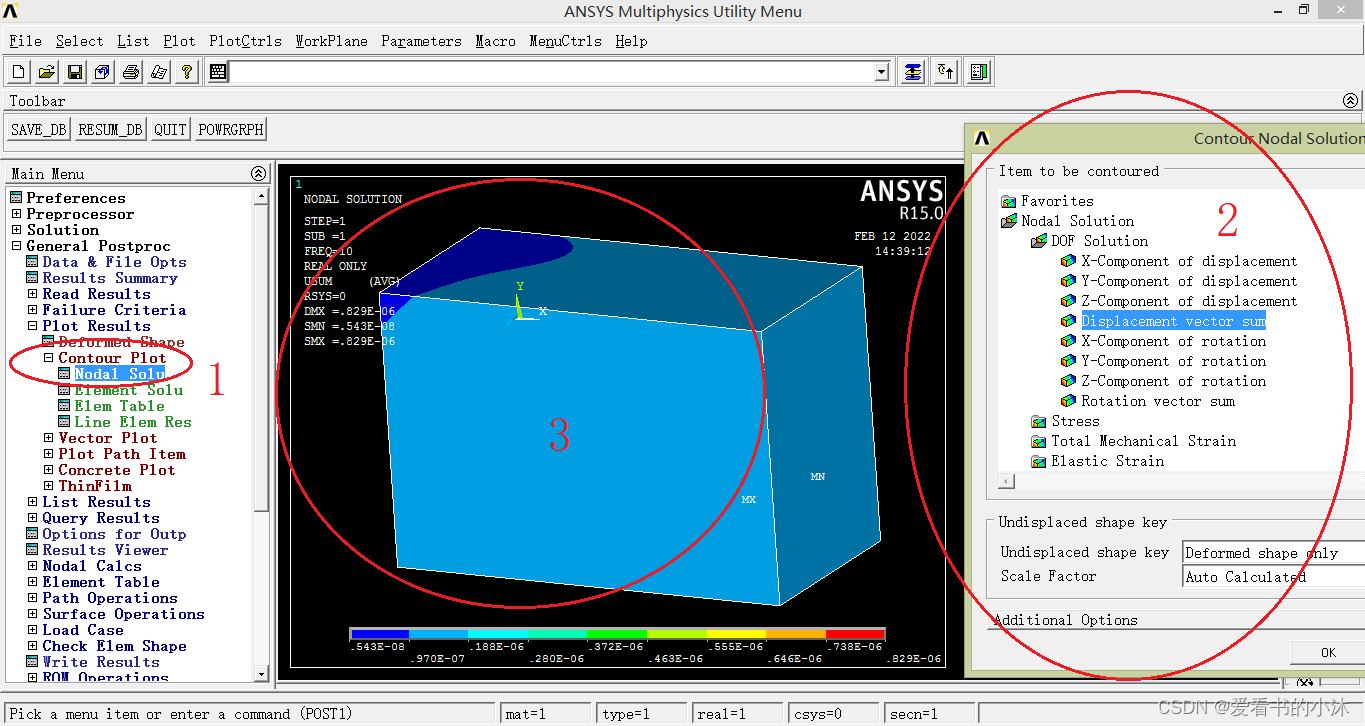
绘制单元的位移等值线图: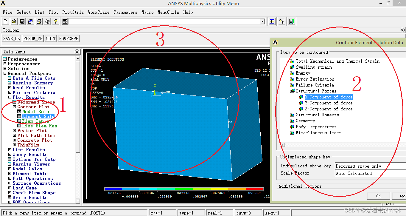
绘制位移的 矢量图 :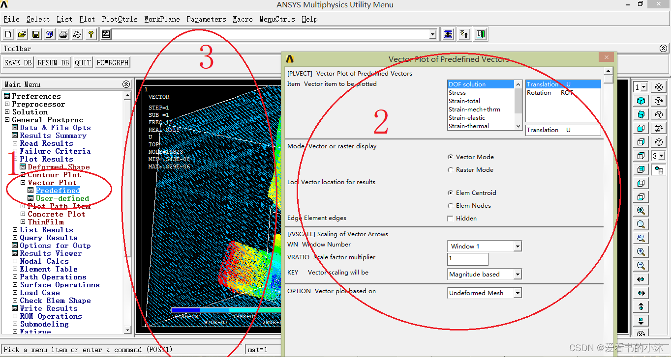
只绘制单元图: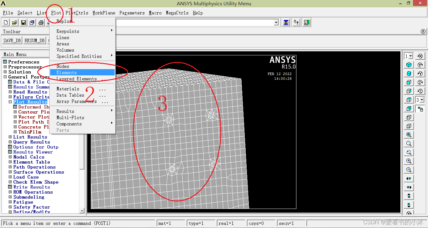
只绘制节点图: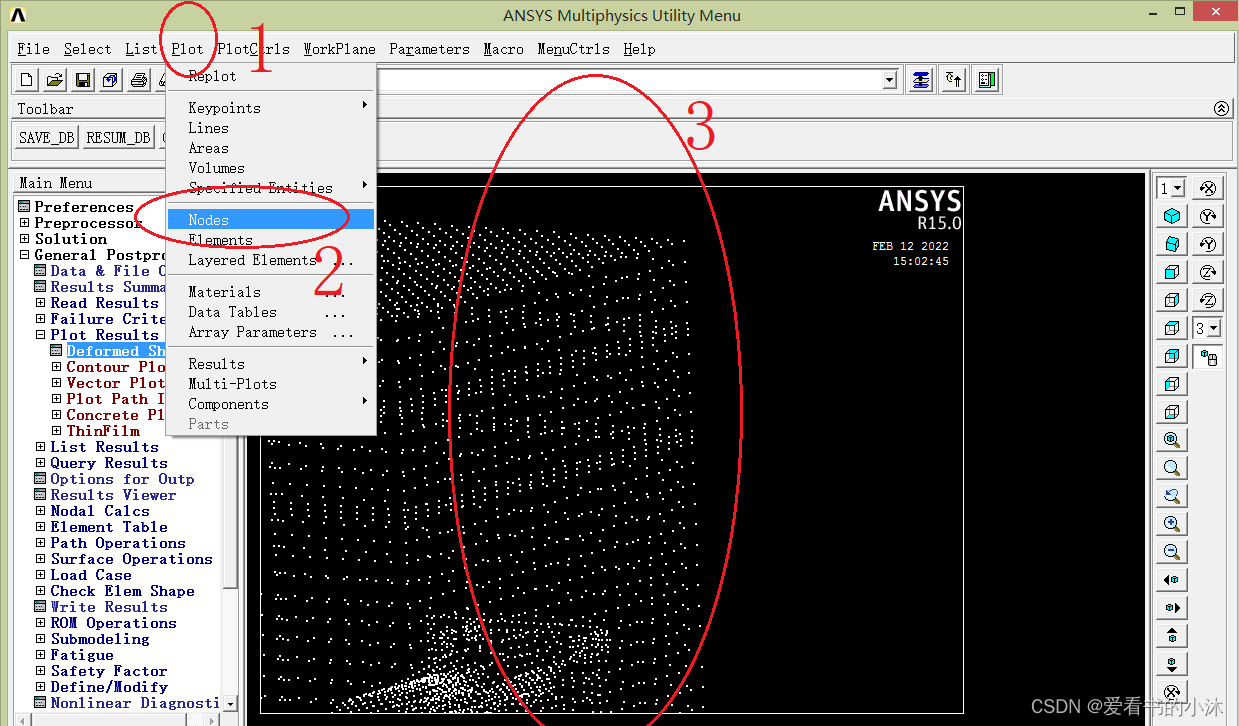
eplot ! 或 gplot、nplot、 kplot
/view, 1, 1,1,1
/replot
说明:
gplot: 各元素综合显示
kplot: 显示选择的关键点
lplot:显示选择的线
aplot:显示选择的面
vplot:显示选择的体
nplot:显示选择的节点
eplot:显示选择的单元
plnsol,u,x
plnsol,u,y
plnsol,u,z
plnsol,u,sum

plesol,u,x
plesol,u,y
plesol,u,z
plesol,u,sum

plvect,u $ plvect,s

/contour,,18,-16,,500
set,first
pldisp,0
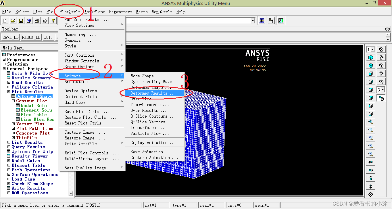
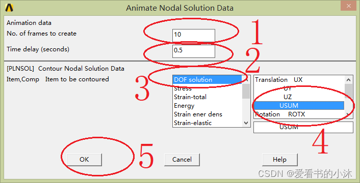
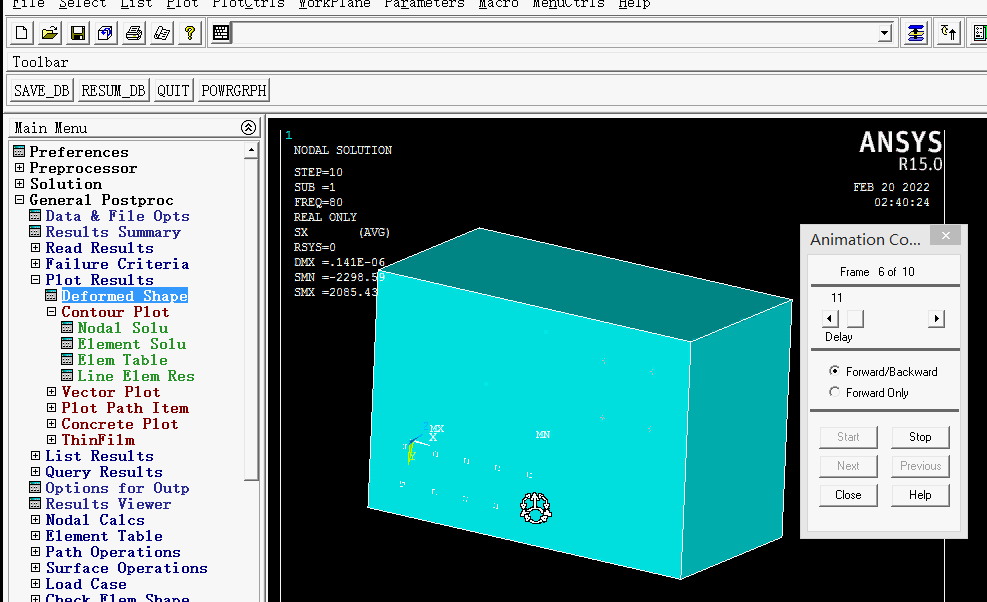
anmode,10,0.5e-1
对等值位移图的动画制作,utility meun-》plotctrls-》animate-》deformed results,输入帧数为10, 时间间隔 为0.5秒。
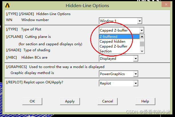
Display type. Defaults to ZBUF for raster mode displays or BASIC for vector mode displays:
| Value | Description |
|---|---|
| BASIC or 0 | Basic display (no hidden or section operations). |
| SECT or 1 | Section display (plane view). Use the /CPLANE command to define the cutting plane. |
| HIDC or 2 | Centroid hidden display (based on item centroid sort). |
| HIDD or 3 | Face hidden display (based on face centroid sort). |
| HIDP or 4 | Precise hidden display (like HIDD but with more precise checking). Because all facets are sorted, this mode can be extremely slow, especially for large models. |
| CAP or 5 | Capped hidden display (same as combined SECT and HIDD with model in front of section plane removed). |
| ZBUF or 6 | Z-buffered display (like HIDD but using software Z-buffering). |
| ZCAP or 7 | Capped Z-buffered display (same as combined SECT and ZBUF with model in front of section plane removed). |
| ZQSL or 8 | QSLICE Z-buffered display (same as SECT but the edge lines of the remaining 3-D model are shown). |
| HQSL or 9 | QSLICE precise hidden display (like ZQSL but using precise hidden). |
/TYPE,1,6 ! Z-buffered display
/TYPE,1,5 ! Capped hidden display
/TYPE,1,7 ! Capped Z-buffered display
该命令仅仅用于截面和加盖显示。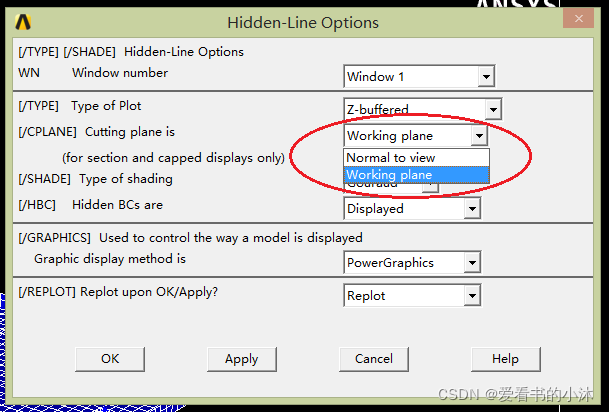
Specifies the cutting plane:
| Value | Description |
|---|---|
| 0 | Cutting plane is normal to the viewing vector [/VIEW] and passes through the focus point [/FOCUS] (default). |
| 1 | The working plane [WPLANE] is the cutting plane. |
!0: Normal to view
/CPLANE, 0

!1: Working plane
/CPLANE, 1
转动 模型 ,就可以看到相应截面的结果图。这个截面始终平行面向用户屏幕。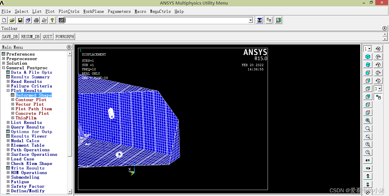
! Normal to view
/CPLANE, 0
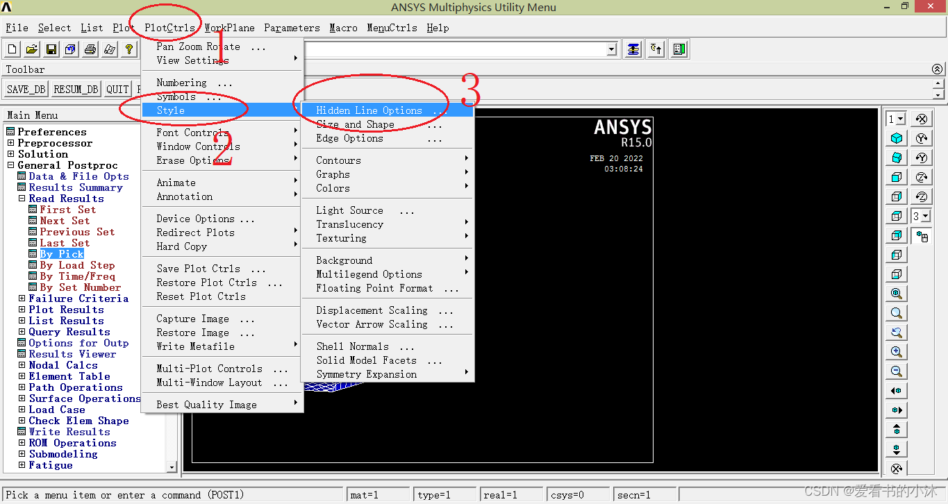
需要自定义工作平面,来显示截图。通过菜单Utility Menu -> WorkPlane。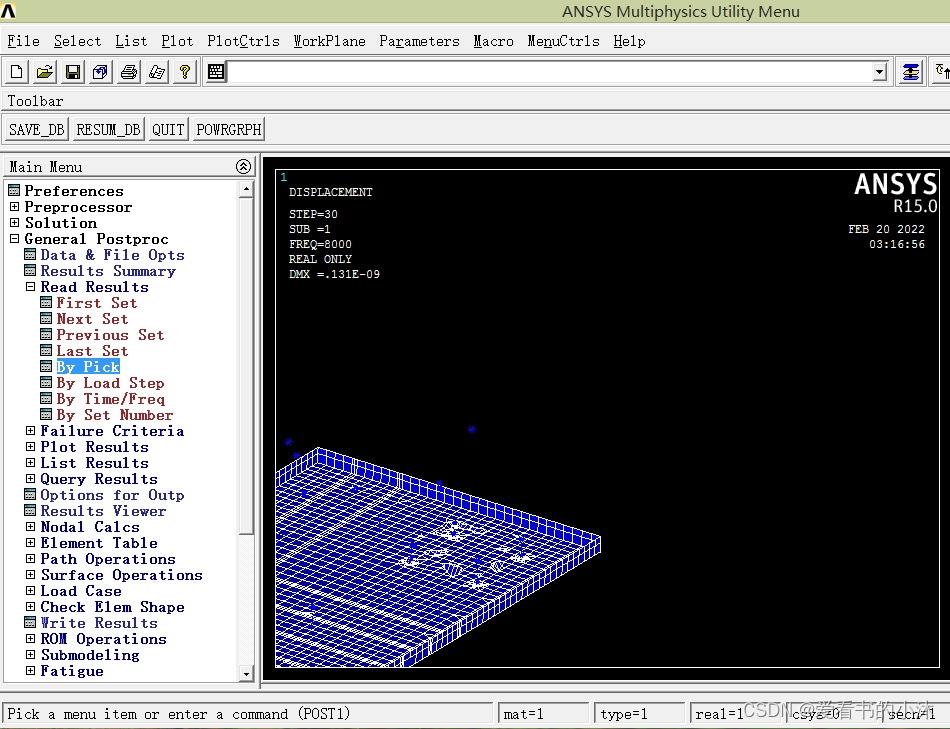
! Working plane
/CPLANE,1 ! Cutting plan


爱阅读的小沐技术探讨 / 代码分享 / 软件定制 / 阅读感悟
免责声明:本文系网络转载或改编,未找到原创作者,版权归原作者所有。如涉及版权,请联系删
 技术文档
技术文档
 推荐好文
推荐好文


 155-2731-8020


