当前位置:服务支持 >  软件文章 >  Femap to adina螺旋桨分析步骤详解,助力流体动力学研究

Femap to adina螺旋桨分析步骤详解,助力流体动力学研究

阅读数 5
点赞 0
article_banner

xw-prop-movie.gif
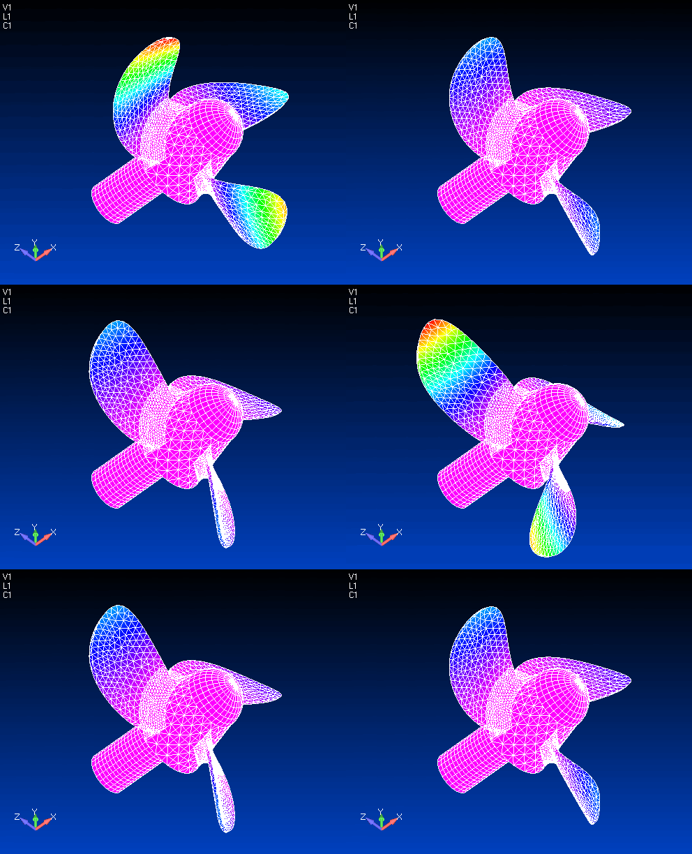
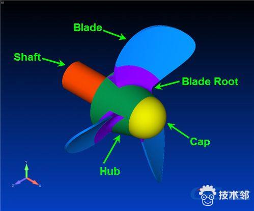
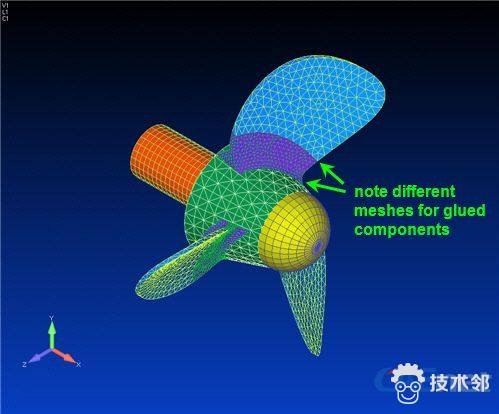
Direct Femap Interface in ADINA — Structural Analysis Example The ADINA User Interface (AUI) program offers comprehensive pre- and post-processing capabilities for the complete suite of ADINA Solution programs – Structures, Thermal, CFD, Electromagnetics and Multiphysics. However, other third-party pre- and post-processors can also work with the ADINA solvers and may offer certain advantages. For example, Femap contains interfaces to certain CAD packages not currently supported by the AUI, such as interfaces to ACIS, CATIA and Pro/ENGINEER (now called Creo Elements/Pro). With the direct Femap interface in ADINA, users can benefit from their familiarity with Femap and leverage the advantages of Femap in pre- and post-processing with the powerful features of the ADINA solvers. In this Brief, we demonstrate the direct Femap interface in ADINA for a propeller model that involves glueing (which allows different meshes for the glued components), contact and a preload bolt in static analysis followed by a frequency analysis. Figure 1 shows the geometry of the assembly of the propeller model with five components. The bottom of the shaft is fixed and centrifugal loading is applied to the whole model. In addition, pressure load is applied to the three blades.
xw-prop-fig_1.jpg

Figure 1 Schematic of propeller model
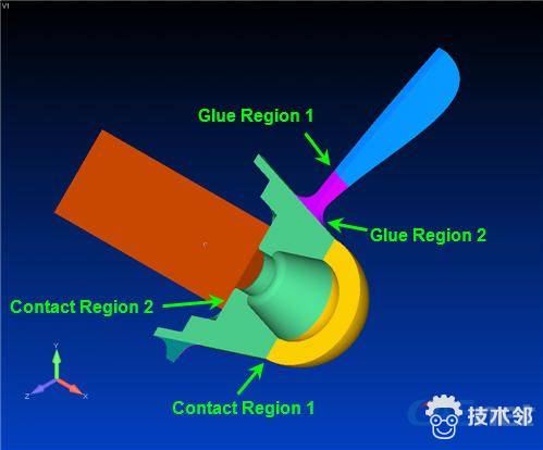
As shown in Figure 2, the first glue region is between the blade and blade root and the second one is between the blade root and outer surface of the hub. Two contact regions are also defined between the bottom of the cap and the top of the hub as well as the top of the shaft and the bottom of the hub. In addition, a bolt element (not shown in Figure 2) is employed to connect the cap and the shaft with a preload.
xw-prop-fig_2.jpg

Figure 2 Locations of contact and glue regions
We demonstrate the ease of using the direct Femap interface in ADINA with the following step-by-step analysis. Step 1: Import the geometry model into Femap and clean it up Step 2: Define the material properties and mesh with 3D solid elements
xw-prop-step_2.jpg

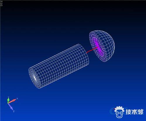
Step 3: Create bolt element and rigid elements that connect the cap and hub to the bolt element
xw-prop-step_3.jpg

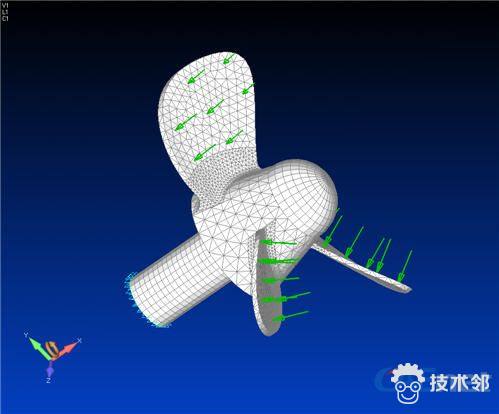
Step 4: Apply bolt preload, body load of rotational velocity in global X direction and pressure load on the three blades
xw-prop-step_4.jpg

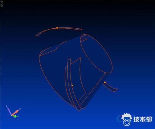
Step 5: Apply constraints at the bottom of the shaft and fix the rotation DOFs of the bolt element Step 6: Define the glueing property with default values. Create the glue regions and the corresponding connectors of glueing
xw-prop-step_6.jpg

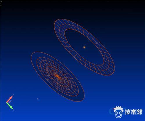
Step 7: Define the contact property with "Friction Param 1=0.2". Create contact regions and the corresponding connectors of contact
xw-prop-step_7.jpg

Step 8: Perform the nonlinear static analysis using the direct Femap interface in ADINA Enter the Job Name and Heading (if desired) in the ADINA Analyze window, select options as shown, and run ADINA to solve the model.
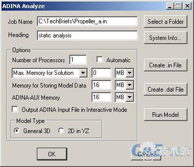
xw-prop-step_8.jpg

Step 9: Define settings for frequency/modes analysis Set "Number of Frequency/Mode Shapes" equal to 10.
xw-prop-step_9.jpg


免责声明:本文系网络转载或改编,未找到原创作者,版权归原作者所有。如涉及版权,请联系删
相关文章
QR Code
微信扫一扫,欢迎咨询~

联系我们
武汉格发信息技术有限公司
湖北省武汉市经开区科技园西路6号103孵化器
电话:155-2731-8020 座机:027-59821821
邮件:tanzw@gofarlic.com
Copyright © 2023 Gofarsoft Co.,Ltd. 保留所有权利
遇到许可问题?该如何解决!?
评估许可证实际采购量? 
不清楚软件许可证使用数据? 
收到软件厂商律师函!?  
想要少购买点许可证,节省费用? 
收到软件厂商侵权通告!?  
有正版license,但许可证不够用,需要新购? 
联系方式 155-2731-8020
预留信息,一起解决您的问题
* 姓名:
* 手机:

* 公司名称:

姓名不为空

手机不正确

公司不为空